Early Lecher line

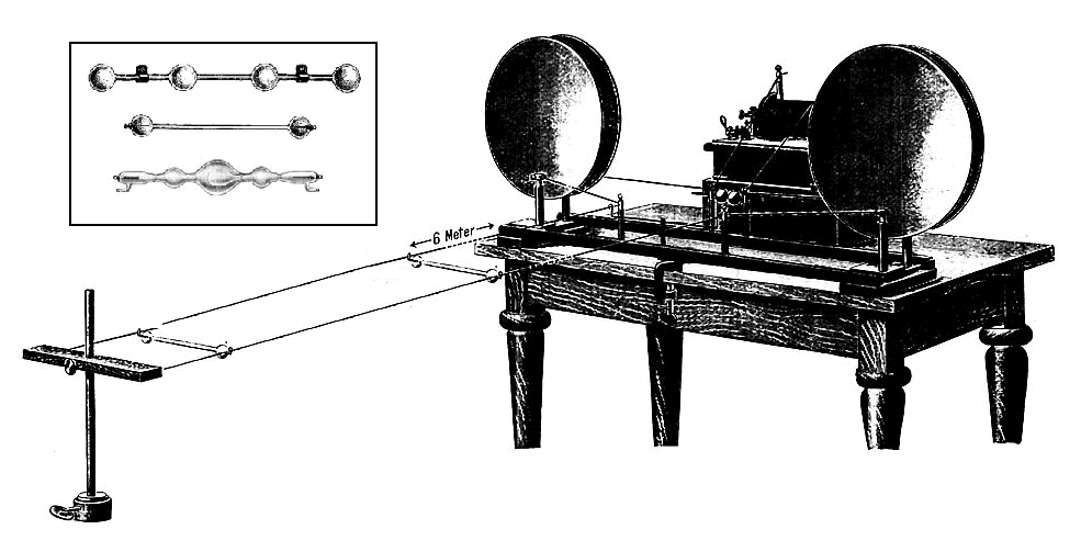
To find the location of the nodes, a Geissler tube, similar to a small neon light, is suspended from hooks across the line and slid up and down the line. The high voltage waves cause it to glow. At the nodes the voltage goes to zero so the Geissler tube goes out. The inset (top left) shows the type of Geissler tubes that were used with Lecher lines.
The Hertzian oscillator (right) generated radio waves in the UHF range, with wavelengths of a few meters, so a 6 meter Lecher line was used (the length is truncated in this drawing). The oscillator consists of an induction coil that generates a high voltage that jumps across a spark gap (center) many times per second. The two sides of the spark gap are coupled to the Lecher line through two parallel-plate capacitors (circles). The energy stored in the capacitors is discharged into the line during each spark, generating a brief oscillating radio wave (damped wave) that decays to zero. The symmetrical balanced circuit ensures that equal and opposite voltage waves are induced in each wire.
Alterations to image: extended the length of the Lecher line, which was misleadingly shortened to several inches long in the original drawing to save space. Added inset showing closeup of Geissler tubes from nearby drawing in same source.Więcej informacji o licencji można znaleźć tutaj. Ostatnia aktualizacja: Thu, 05 Aug 2021 09:54:39 GMT