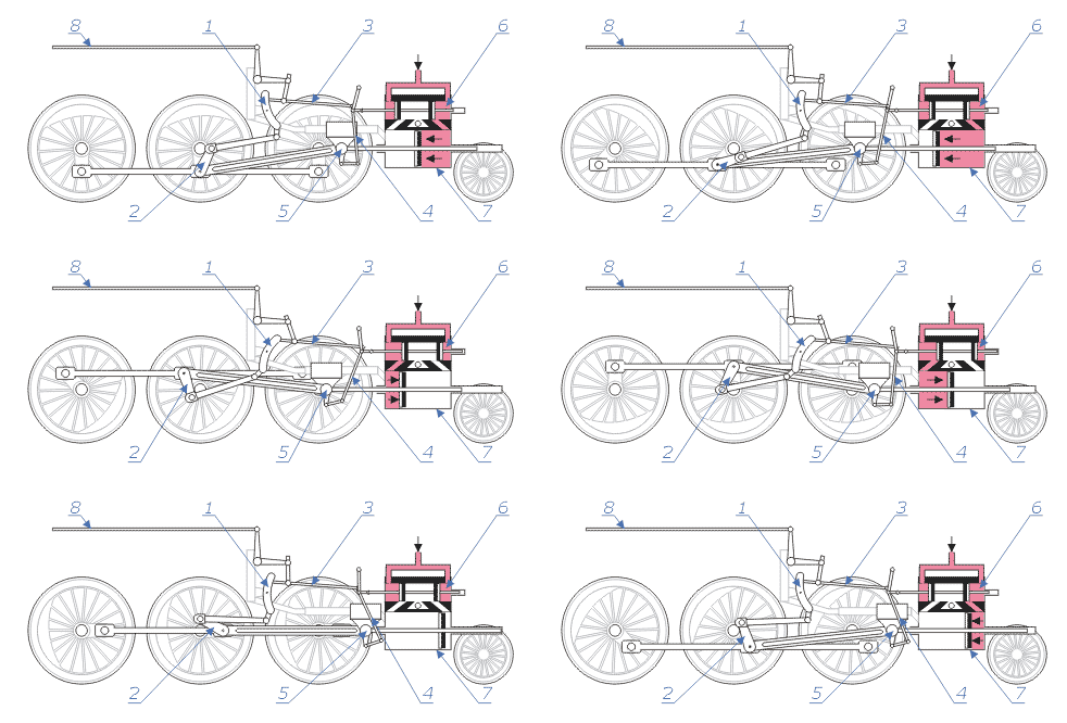
Silnik parowozu
Silnik parowozu jest specyficzną maszyną parową.
Maszynista może sterować silnikiem parowozu poprzez:
- ustawienie nastawnika (czyli pośrednio stawidła) - regulatora ruchu suwaka (zmiana fazy rozrządu pary) i regulatora stopnia napełniania cylindra parą.
- ustawienie przepustnicy i regulacja ciśnienia pary podawanej do cylindrów.
Za pomocą nastawnika można regulować zarówno kierunek ruchu kół (jazda do przodu lub do tyłu), jak i siłę napędową przekazywaną z tłoczyska poprzez korbowód na koła. Ustawienia stawidła poprzez drąg stawidłowy (8) decyduje o ruchu wodzika suwaka (3) i samego suwaka, który otwiera dopływ pary do tłoka. W położeniu neutralnym stawidło tak ustawia wodzik, że suwak w ogóle się nie porusza, a zatem para nie jest podawana do tłoków.
Ruszenie parowozem wymaga ustawienia nastawnika (stawidła) maksymalnie (na największe napełnienie) w jednym kierunku (do przodu lub do tyłu) i lekkim otwarciu przepustnicy. W miarę jak parowóz nabiera prędkości, maszynista przesuwa stawidło w kierunku położenia neutralnego (zmniejszając współczynnik napełnienia) i (możliwie szybko) zwiększając ciśnienie przepustnicą (aby nie było strat na dławienie przepływu pary z kotła do cylindra) pozwalając tym samym na większe wykorzystanie energii rozprężania pary. Dzięki temu parowóz może nabrać prędkości i nie zużywa dużej ilości pary a tym samym paliwa potrzebnego na jej wytworzenie. Przy dużym napełnieniu i dużym ciśnieniu na rozrządzie zwykle dochodzi do zerwania przyczepności kół z torem (tzw. buksowanie).
Zwykle w momencie ruszania ze składem napełnienie cylindrów parą sięga 70-80%, w czasie ustalonej prędkości na szlaku (bez wzniesień) napełnienie sięga minimum, ok. 25-28% skoku tłoka. Przy cięższych składach konieczna bywa jazda z napełnieniem ok. 40%, większego napełnienia wymaga też prowadzenie składu podczas podjazdu na wzniesienie.
Media użyte na tej stronie
Autor: Panther, Licencja: CC-BY-SA-3.0
Steam locomotive wheels, valve & engine animation.
Walschaerts valve gear (mechanism for moving the valve in a steam engine).
Item 2 is a crank outside of the main crankpin. Its "timing" is a quarter turn away from the power crankpin. This provides the main force to move the valve.
Item 1 is pivoted (little dot, just below the callout arrow) to the frame (light gray) in the middle, so it rocks back and forth. It has a groove (inside; not shown) along its length, which carries a sliding block, pivoted on the left end of link 3. The engineer moves pushrod 8 left and right to move link 3 up and down.
If the link is below center, the engine moves backwards. If the link is near to the center, steam is conserved for ordinary running when up to speed.
The short link below the numeral 3 (not the arrow) that seems to point up into the air "from the wheel edge" is pivoted on the frame (not shown) at its upper end. It supports the rest of the links below it. The right end of link 3, therefore, doesn't move up and down much; its sidewise motion operates the valve.
Item 4 is the crosshead, the sliding piece that guides the piston rod. (Callout 4 also points to a link that improves valve timing.)
Note the typically-European piston rod -- it's very long, and unlike American (and some other) designs, it extends out front (to the right). The other types of locos. don't have any piston rod to the right side of the piston.
Item 5 is the pivot where the main connecting rod (long groove. shown, to make it lighter) connects to the crosshead.
Item 6 is the cylinder and valve block. Pinkish color is steam from the boiler. Exhaust is white. The valve is a pair of black vertical stripes, connected together. (It's shaped something like a spool.)
As shown (without animation), steam is going into the right side of the cylinder (Item 7), pushing the piston to the left. The piston rod pushes the crosshead, which pushes the main connecting rod. (The piston is in the middle of the cylinder. Unlike pistons in internal-combustion engines, steam pistons are discs.)


