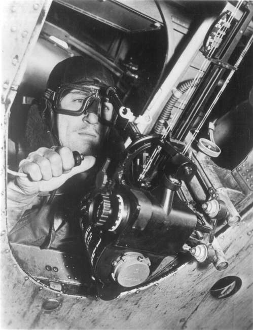
Course Setting Bomb Sight in use
This image shows a number of the main features of the sight. At the rear of the device, near the bottom of the image, is the vertical cylinder of the compass assembly. The horizontal metal section in front of the compass assembly, roughly triangular, is the "airspeed drum", used to set the aircraft's airspeed via the large knob on the right side of the case, directly under the bomb aimer's hand. Extending from the front of the airspeed drum is the airspeed bar and windspeed assembly. In this case the airspeed has been set to its minimum value, so the windspeed assembly is lying directly against the housing and is not clearly visible. This also explains the almost vertical angle formed between the sights; with this airspeed setting the bombs would not travel forward very far during the drop. Looking carefully, one can see the "wind bar" at the top of the windspeed assembly, the black metal bar lying almost at right angles to the rest of the bomb sight. Turning the wind speed knob on the end of the bar (not visible here, it's on the other side of the bar) would push the entire drift bar to the right to dial-in increasing correction for a wind blowing from the right side of the aircraft. The long striped wires above this assembly form the drift bar, which indicates which direction the aircraft should fly to correct for wind drift. In this case the drift bar is pointed very slightly to the bomb aimer's left, accounting for a wind from port.
Secondary details are also visible. The grey disk on the bottom of the compass assembly is the compass corrector, which reduces the effect of stray magnetic fields from the aircraft body. The small grey knob directly above the airspeed setting knob is used to set the "trail", the distance that the bomb will fall behind the aircraft when it reaches terminal velocity. Just to the right of this (in the photograph) is a large horizontal ring that makes up the moving target assembly (or "fourth vector"). To the right of the air speed drum are two of three silver coloured bolts of the flexible mounting system, which is used to level the bombsight prior to use. The small beads used for timing can just be seen on the drift wires. At the front, on the very top-right of the image, is the scale on the auxiliary drift bar, which is used to make quick measurements of wind drift.
The Battle was supplied with a number of different bombsights for use at different altitudes. They could be exchanged by unscrewing the silver knob on the right side of the photo just to the right of the windspeed assembly, and then sliding the entire bombsight and mounting up and out.
The original label on this photograph states that the bombsight is a Mk. IX model. However, this model was designed for high-speed aircraft like the B-25 and Mosquito. It is much more likely that this is a mis-labeled Mk. VII, the primary pre-war model that would have equipped the Battle in service. The differences between the two models are largely limited to the scales on the drift and height bars to account for faster speeds and higher altitudes. The two are identical to the eye.Więcej informacji o licencji można znaleźć tutaj. Ostatnia aktualizacja: Fri, 29 Jul 2022 08:01:33 GMT